首页 / 更多教程 / 基于SCCB协议的FPGA实现
基于SCCB协议的FPGA实现
内容导读
互联网集市收集整理的这篇技术教程文章主要介绍了基于SCCB协议的FPGA实现,小编现在分享给大家,供广大互联网技能从业者学习和参考。文章包含13820字,纯文字阅读大概需要20分钟。
内容图文

SCCB协议
1、协议内容
SCCB协议常用于vo系列的摄像头的寄存器配置中,是有IIC协议演变而来。本来,本人接触这个协议也是想配置摄像头用于摄像模块。但是,由于配置寄存器实在是太多,而且需要找的资料也比较多,就放弃了,以后有时间再去完成吧。现在先将SCCB协议的设计过程记录下来,方便以后查找。
SCCB协议的内容和IIC协议的内容大致相似。有开始位、数据位和结束位。只不过开始位和结束位的形式还是有所不同的。当然,这里指的是双线的SCCB协议,至于三线的协议,只是了解过,感兴趣可以在网上查一下。
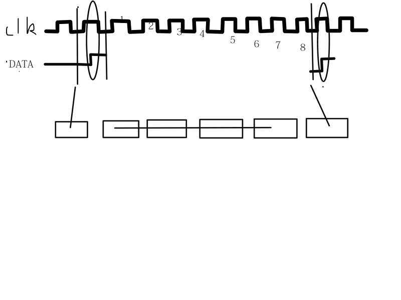
这里是一相数据的简图(图中应该有九个数据,由于前期理解不到位认为是八个)。可以看到除了开始位和结束位发生了“错位”,其他的类型和IIC基本一样。
在SCCB中,一次完整的传输不是以一相为单位的,而是两相或三相为单位的。两相是用于读取数据,而三相则是用于写入数据。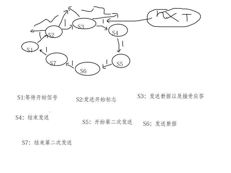
这是设计时画的状态机简图,还是比较简单的,七个状态单个循环就可以实现。具体的时间间隔在代码中有,可以从数据手册中可以找到最小值。这里不做过多的细节介绍。
同理,写操作还要比读简单,只需要一次三相操作即可。只需要将状态机的状态数减为4,将数据传输状态的有两相改为三相即可。这里在代码中会有具体的体现。
2、FPGA设计(verilog)
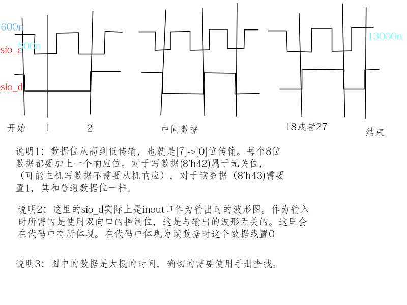
从前面的简介看还是比较简单的,但是细节还是比较多,下面给一张细节图供后续的设计。
前面提到了使用状态机实现,自然需要构建状态机。
            module
             sccb_read (

            input
             clk,

            input
             rst_n,

            input
             work,

            output
             work_end,


            input
             sio_din,

            output
            reg
             sio_dcr,

            output
            reg
             sio_c,

            output
            reg
             sio_dout,

            output
            reg [7:0] data_get
);
localparam D3000=3000;
localparam D1500=D3000/2;
localparam Cnt_D1500=D1500/20;
localparam Cnt_D3000=D3000/20;
localparam T54000n=Cnt_D3000*19;
localparam T15000n=Cnt_D3000*10;
localparam S1=4‘d0;localparam S2=4‘d1;localparam S3=4‘d2;localparam S4=4‘d3;localparam S5=4‘d4;localparam S6=4‘d5;localparam S7=4‘d6;wire [8:0] id;
    wire [8:0] ad;
    wire [8:0] id2;
    assign id={8‘h42,1‘b0};
    assign ad={8‘h03,1‘b0};
    assign id2={8‘h43,1‘b0};

    reg [3:0] state_now;
    reg [3:0] state_nxt;
    reg [7:0] cnt_wait;
    reg [7:0] cnt_start;
    reg [11:0] cnt_data;
    reg [11:0] cnt_stop;
    reg [7:0] cnt_start2;
    reg [11:0] cnt_data2;
    reg [11:0] cnt_stop2;

    reg [4:0] cnt_site;
    reg [7:0] cnt_clk;
always@(posedge clk ornegedge rst_n)beginif(!rst_n)begin
        state_now<=S1;
    endelsebegincase(state_now)
            S1: if(work && cnt_wait==Cnt_D3000-1‘b1)state_now<=state_nxt;
            S2: if(cnt_start==Cnt_D3000-1‘b1)state_now<=state_nxt;
            S3: if(cnt_data==T54000n-1‘b1)state_now<=state_nxt;
            S4: if(cnt_stop==T15000n-1‘b1)state_now<=state_nxt;
            S5: if(cnt_start2==Cnt_D3000-1‘b1)state_now<=state_nxt;
            S6: if(cnt_data2==T54000n-1‘b1)state_now<=state_nxt;
            S7: if(cnt_stop2==T15000n-1‘b1)state_now<=state_nxt;endcaseendendalways@(*)begincase(state_now)
        S1: state_nxt<=S2;
        S2: state_nxt<=S3;
        S3: state_nxt<=S4;
        S4: state_nxt<=S5;
        S5: state_nxt<=S6;
        S6: state_nxt<=S7;
        S7: state_nxt<=S1;
    endcaseendalways@(posedge clk ornegedge rst_n)beginif(!rst_n)begin
        cnt_wait<=1‘b0;endelseif(cnt_wait==Cnt_D3000)begin
        cnt_wait<=1‘b0;endelseif(state_now==S1 )beginif(work)begin
        cnt_wait<=cnt_wait+1‘b1;endendelsebegin
        cnt_wait<=1‘b0;endendalways@(posedge clk ornegedge rst_n)beginif(!rst_n)begin
        cnt_start<=1‘b0;endelseif(cnt_start==Cnt_D3000-1‘b1) begin
        cnt_start<=1‘b0;endelseif(state_now==S2)begin
        cnt_start<=cnt_start+1‘b1;endelsebegin
        cnt_start<=1‘b0;endendalways@(posedge clk ornegedge rst_n)beginif(!rst_n)begin
        cnt_data<=1‘b0;endelseif(cnt_data==T54000n -1‘b1)begin
        cnt_data<=1‘b0;endelseif(state_now==S3 ) begin
        cnt_data<=cnt_data+1‘b1;endelsebegin
        cnt_data<=1‘b0;endendalways@(posedge clk ornegedge rst_n)beginif(!rst_n)begin
        cnt_stop<=1‘b0;endelseif(cnt_stop==T15000n-1‘b1) begin
        cnt_stop<=1‘b0;endelseif(state_now==S4)begin
        cnt_stop<=cnt_stop+1‘b1;endelsebegin
        cnt_stop<=1‘b0;endendalways@(posedge clk ornegedge rst_n)beginif(!rst_n)begin
        cnt_start2<=1‘b0;endelseif(cnt_start2==Cnt_D3000-1‘b1) begin
        cnt_start2<=1‘b0;endelseif(state_now==S5)begin
        cnt_start2<=cnt_start2+1‘b1;endelsebegin
        cnt_start2<=1‘b0;endendalways@(posedge clk ornegedge rst_n)beginif(!rst_n)begin
        cnt_data2<=1‘b0;endelseif(cnt_data2==T54000n -1‘b1)begin
        cnt_data2<=1‘b0;endelseif(state_now==S6 ) begin
        cnt_data2<=cnt_data2+1‘b1;endelsebegin
        cnt_data2<=1‘b0;endendalways@(posedge clk ornegedge rst_n)beginif(!rst_n)begin
        cnt_stop2<=1‘b0;endelseif(cnt_stop2==T15000n-1‘b1) begin
        cnt_stop2<=1‘b0;endelseif(state_now==S7)begin
        cnt_stop2<=cnt_stop2+1‘b1;endelsebegin
        cnt_stop2<=1‘b0;endend
这里是状态机的主体部分和驱动部分。由于这个协议的时间是有具体的要求,所以这里所有的状态转化都是基于特定的时间长度来构建的,而不是采用控制方式。除了第一个状态是需要外部驱动,其他的状态都是可以基于时间自行运转的,这也简化了后续的仿真时的难度。那个部分的状态不对可以直接对应到时间上,而不是去判断多个判断信号。本人认为这段代码还是比较基础的,就没有加上注释。
            always@(posedge clk ornegedge rst_n)beginif(!rst_n)begin
        cnt_clk<=1‘b0;endelseif(cnt_clk==Cnt_D1500-1‘b1)begin
        cnt_clk<=1‘b0;endelseif(state_now==S3 || state_now== S6) begin
        cnt_clk<=cnt_clk+1‘b1;endelsebegin
        cnt_clk<=1‘b0;endendalways@(posedge clk ornegedge rst_n)beginif(!rst_n)begin
        sio_c<=1‘b1;endelsebegincase(state_now)
            S1:sio_c<=1‘b1;
            S2:sio_c<=1‘b1;
            S3:if(cnt_clk==Cnt_D1500-1‘b1)sio_c=~sio_c;
            S4:sio_c<=1‘b1;
            S5:sio_c<=1‘b1;
            S6:if(cnt_clk==Cnt_D1500-1‘b1)sio_c=~sio_c;
            S7:sio_c<=1‘b1;endcaseendendalways@(posedge clk ornegedge rst_n)beginif(!rst_n)begin
        cnt_site<=1‘b0;endelseif(state_now==S3 || state_now==S6) beginif(cnt_clk==Cnt_D1500/2-1‘b1 && sio_c==1‘b0 )begin
            cnt_site<=cnt_site+1‘b1;endelsebegin
            cnt_site<=cnt_site;
        endendelsebegin
        cnt_site<=1‘b0;endendalways@(posedge clk ornegedge rst_n)beginif(!rst_n)begin
        sio_dout<=1‘b1;endelsebegincase(state_now)
            S1:sio_dout<=1‘b1;
            S2:if(cnt_start==Cnt_D1500-1‘b1)sio_dout<=1‘b0;
            S3:begincase(cnt_site)
                    5‘d0:sio_dout<=sio_dout;5‘d1:sio_dout<=id[8];5‘d2:sio_dout<=id[7];5‘d3:sio_dout<=id[6];5‘d4:sio_dout<=id[5];5‘d5:sio_dout<=id[4];5‘d6:sio_dout<=id[3];5‘d7:sio_dout<=id[2];5‘d8:sio_dout<=id[1];5‘d9:sio_dout<=id[0];5‘d10:sio_dout<=ad[8];5‘d11:sio_dout<=ad[7];5‘d12:sio_dout<=ad[6];5‘d13:sio_dout<=ad[5];5‘d14:sio_dout<=ad[4];5‘d15:sio_dout<=ad[3];5‘d16:sio_dout<=ad[2];5‘d17:sio_dout<=ad[1];5‘d18:sio_dout<=ad[0];5‘d19:sio_dout<=1‘b0;
                    default:sio_dout<=sio_dout;
                endcaseend
            S4:if(cnt_stop==Cnt_D1500-1‘b1)sio_dout<=1‘b1;
            S5:if(cnt_start2==Cnt_D1500-1‘b1)sio_dout<=1‘b0;
            S6:begincase(cnt_site)
                    5‘d0:sio_dout<=sio_dout;5‘d1:sio_dout<=id2[8];5‘d2:sio_dout<=id2[7];5‘d3:sio_dout<=id2[6];5‘d4:sio_dout<=id2[5];5‘d5:sio_dout<=id2[4];5‘d6:sio_dout<=id2[3];5‘d7:sio_dout<=id2[2];5‘d8:sio_dout<=id2[1];5‘d9:sio_dout<=id2[0];5‘d18:sio_dout<=1‘b1;
                    5‘d19:sio_dout<=1‘b0;
                    default:sio_dout<=sio_dout;
                endcaseend
            S7:if(cnt_stop2==Cnt_D1500-1‘b1)sio_dout<=1‘b1;
        endcaseendendalways@(posedge clk ornegedge rst_n)beginif(!rst_n)begin
        sio_dcr<=1‘b1;endelsebegincase(state_now)
            S1:sio_dcr<=1‘b1;
            S2,S3,S4,S5,S7:sio_dcr<=1‘b1;
            S6:if(5‘d9<cnt_site && cnt_site<5‘d18)sio_dcr<=1‘b0;else sio_dcr<=1‘b1;
        endcaseendendalways@(posedge clk ornegedge rst_n)beginif(!rst_n)begin
        data_get<=8‘b1111_1111;endelseif(state_now==S6 && cnt_clk==Cnt_D1500/2-1‘b1 && sio_c==1‘b1 ) begincase(cnt_site)
            5‘d10: data_get[7]<=sio_din;5‘d11: data_get[6]<=sio_din;5‘d12: data_get[5]<=sio_din;5‘d13: data_get[4]<=sio_din;5‘d14: data_get[3]<=sio_din;5‘d15: data_get[2]<=sio_din;5‘d16: data_get[1]<=sio_din;5‘d17: data_get[0]<=sio_din;endcaseendendassign work_end=(state_now==S7 && cnt_stop2==T15000n-1‘b1);endmodule
这段代码则是有了状态机的基础上,针对所需的输出,构建的输出模型。具体的比较复杂,我也记不大清楚细节。大致看一下,最好自己写。这是SCCB实现的关键逻辑。
至于写模块就是这个模块的删减和增加,直接上代码即可:
            module
             sccb_write (

            input
             clk,

            input
             rst_n,

            input
             work,

            input [15:0] data_sum,
    output work_end,
//    input sio_din,outputreg sio_dcr,
    outputreg sio_c,
    outputreg sio_dout
);
localparam D3000=3000;
localparam D1500=D3000/2;
localparam Cnt_D1500=D1500/20;
localparam Cnt_D3000=D3000/20;
localparam T81000n=Cnt_D3000*28;
localparam T15000n=Cnt_D3000*10;
localparam S1=4‘d0;localparam S2=4‘d1;localparam S3=4‘d2;localparam S4=4‘d3;  wire [8:0] id;
    wire [8:0] ad;
    wire [8:0] da;
    assign id={8‘h42,1‘b0};
    assign ad={data_sum[15:8],1‘b0};assign da={data_sum[7:0],1‘b0}; reg [1:0] state_now;
    reg [1:0] state_nxt;
     reg [7:0] cnt_wait;
    reg [7:0] cnt_start;
    reg [14:0] cnt_data;
    reg [11:0] cnt_stop;

    reg [4:0] cnt_site;
    reg [7:0] cnt_clk;
always@(posedge clk ornegedge rst_n)beginif(!rst_n)begin
        state_now<=S1;
    endelsebegincase(state_now)
            S1: if(work && cnt_wait==Cnt_D3000-1‘b1)state_now<=state_nxt;
            S2: if(cnt_start==Cnt_D3000-1‘b1)state_now<=state_nxt;
            S3: if(cnt_data==T81000n-1‘b1)state_now<=state_nxt;
            S4: if(cnt_stop==T15000n-1‘b1)state_now<=state_nxt;    endcaseendendalways@(*)begincase(state_now)
        S1: state_nxt<=S2;
        S2: state_nxt<=S3;
        S3: state_nxt<=S4;
        S4: state_nxt<=S1;
    endcaseendalways@(posedge clk ornegedge rst_n)beginif(!rst_n)begin
        cnt_wait<=1‘b0;endelseif(cnt_wait==Cnt_D3000)begin
        cnt_wait<=1‘b0;endelseif(state_now==S1 )beginif(work)begin
        cnt_wait<=cnt_wait+1‘b1;endendelsebegin
        cnt_wait<=1‘b0;endendalways@(posedge clk ornegedge rst_n)beginif(!rst_n)begin
        cnt_start<=1‘b0;endelseif(cnt_start==Cnt_D3000-1‘b1) begin
        cnt_start<=1‘b0;endelseif(state_now==S2)begin
        cnt_start<=cnt_start+1‘b1;endelsebegin
        cnt_start<=1‘b0;endendalways@(posedge clk ornegedge rst_n)beginif(!rst_n)begin
        cnt_data<=1‘b0;endelseif(cnt_data==T81000n -1‘b1)begin
        cnt_data<=1‘b0;endelseif(state_now==S3 ) begin
        cnt_data<=cnt_data+1‘b1;endelsebegin
        cnt_data<=1‘b0;endendalways@(posedge clk ornegedge rst_n)beginif(!rst_n)begin
        cnt_stop<=1‘b0;endelseif(cnt_stop==T15000n-1‘b1) begin
        cnt_stop<=1‘b0;endelseif(state_now==S4)begin
        cnt_stop<=cnt_stop+1‘b1;endelsebegin
        cnt_stop<=1‘b0;endendalways@(posedge clk ornegedge rst_n)beginif(!rst_n)begin
        cnt_clk<=1‘b0;endelseif(cnt_clk==Cnt_D1500-1‘b1)begin
        cnt_clk<=1‘b0;endelseif(state_now==S3 ) begin
        cnt_clk<=cnt_clk+1‘b1;endelsebegin
        cnt_clk<=1‘b0;endendalways@(posedge clk ornegedge rst_n)beginif(!rst_n)begin
        sio_c<=1‘b1;endelsebegincase(state_now)
            S1:sio_c<=1‘b1;
            S2:sio_c<=1‘b1;
            S3:if(cnt_clk==Cnt_D1500-1‘b1)sio_c=~sio_c;
            S4:sio_c<=1‘b1;endcaseendendalways@(posedge clk ornegedge rst_n)beginif(!rst_n)begin
        cnt_site<=1‘b0;endelseif(state_now==S3 ) beginif(cnt_clk==Cnt_D1500/2-1‘b1 && sio_c==1‘b0 )begin
            cnt_site<=cnt_site+1‘b1;endelsebegin
            cnt_site<=cnt_site;
        endendelsebegin
        cnt_site<=1‘b0;endendalways@(posedge clk ornegedge rst_n)beginif(!rst_n)begin
        sio_dout<=1‘b1;endelsebegincase(state_now)
            S1:sio_dout<=1‘b1;
            S2:if(cnt_start==Cnt_D1500-1‘b1)sio_dout<=1‘b0;
            S3:begincase(cnt_site)
                    5‘d0:sio_dout<=sio_dout;5‘d1:sio_dout<=id[8];5‘d2:sio_dout<=id[7];5‘d3:sio_dout<=id[6];5‘d4:sio_dout<=id[5];5‘d5:sio_dout<=id[4];5‘d6:sio_dout<=id[3];5‘d7:sio_dout<=id[2];5‘d8:sio_dout<=id[1];5‘d9:sio_dout<=id[0];5‘d10:sio_dout<=ad[8];5‘d11:sio_dout<=ad[7];5‘d12:sio_dout<=ad[6];5‘d13:sio_dout<=ad[5];5‘d14:sio_dout<=ad[4];5‘d15:sio_dout<=ad[3];5‘d16:sio_dout<=ad[2];5‘d17:sio_dout<=ad[1];5‘d18:sio_dout<=ad[0];5‘d19:sio_dout<=da[8];5‘d20:sio_dout<=da[7];5‘d21:sio_dout<=da[6];5‘d22:sio_dout<=da[7];5‘d23:sio_dout<=da[4];5‘d24:sio_dout<=da[3];5‘d25:sio_dout<=da[2];5‘d26:sio_dout<=da[1];5‘d27:sio_dout<=da[0];5‘d28:sio_dout<=1‘b0;
                    default:sio_dout<=sio_dout;
                endcaseend
            S4:if(cnt_stop==Cnt_D1500-1‘b1)sio_dout<=1‘b1;
            endcaseendendalways@(posedge clk ornegedge rst_n)beginif(!rst_n)begin
        sio_dcr<=1‘b0;endelseif(work) begin
        sio_dcr<=1‘b1;endelsebegin
        sio_dcr<=1‘b1;endendassign work_end=(state_now==S4 && cnt_stop==T15000n-1‘b1);endmodule
实现的功能就是一次数据写入。
然后是顶层的模块:
            module
             vo(

            input
             clk,

            input
             rst_n,


            inout
             sio_d,

            output
             sio_c,

            output
             pwdn,

            output
             reset,

            output
             xclk,


            output [7:0] data_get
);
reg work_r;
reg work_w;
wire sio_din;
wire work_end_r;
wire work_end_w;
wire sio_dcr;
wire sio_dcr_r;
wire sio_dcr_w;
wire sio_dout;
wire sio_dout_r;
wire sio_dout_w;
wire sio_c_r;
wire sio_c_w;
reg [15:0] data_sum;

wire locked;
assign sio_d = (sio_dcr) ? sio_dout : 1‘bz;assign sio_din = sio_d;

assign sio_dout = sio_dout_r & sio_dout_w;
assign sio_c = sio_c_r & sio_c_w;
assign sio_dcr = sio_dcr_r & sio_dcr_w;

assign pwdn=1‘b0;assign reset=1‘b1;reg [7:0] cnt_work;

always@(posedge clk ornegedge rst_n)beginif(!rst_n)begin
        cnt_work<=1‘b0;endelseif(cnt_work==8‘d11)begin
        cnt_work<=8‘d11;endelseif(cnt_work==8‘d10 && work_end_r)begin
        cnt_work<=8‘d11;endelseif(work_end_w)begin
        cnt_work<=cnt_work+1‘b1;endendalways@(posedge clk ornegedge rst_n)beginif(!rst_n)begin
        work_w<=1‘b0;endelseif(cnt_work<8‘d10 && locked) begin
        work_w<=1‘b1;endelsebegin
        work_w<=1‘b0;endendalways@(posedge clk ornegedge rst_n)beginif(!rst_n)begin
        work_r<=1‘b0;endelseif(cnt_work==8‘d10 && locked)begin
        work_r<=1‘b1;endelsebegin
        work_r<=1‘b0;endendalways@(posedge clk ornegedge rst_n)beginif(!rst_n)begin
        data_sum<=16‘h1280;endelsebegincase(cnt_work)
            8‘d0:data_sum<=16‘h1280; // reset sccb reg8‘d1:data_sum<=16‘h1101; // raw data half clk8‘d2:data_sum<=16‘h3a04; //8‘d3:data_sum<=16‘h1201; //
8‘d4:data_sum<=16‘h1716;
            8‘d5:data_sum<=16‘h1804;
            8‘d6:data_sum<=16‘h1902;
            8‘d7:data_sum<=16‘h1a7b;
            8‘d8:data_sum<=16‘h3280;
            8‘d9:data_sum<=16‘h0306;
            default:data_sum<=data_sum;
        endcaseendend
pll pll_1(
    .areset(~rst_n),
    .inclk0(clk),
    .c0(xclk),
    .locked(locked)
);
sccb_write m1(
    .clk(clk),
    .rst_n(rst_n),
    .work(work_w),
    .data_sum(data_sum),
    .work_end(work_end_w),
//    input sio_din,    .sio_dcr(sio_dcr_w),
    .sio_c(sio_c_w),
    .sio_dout(sio_dout_w)
);
sccb_read m2(
    .clk(clk),
    .rst_n(rst_n),
    .work(work_r),
    .work_end(work_end_r),

    .sio_din(sio_din),
    .sio_dcr(sio_dcr_r),
    .sio_c(sio_c_r),
    .sio_dout(sio_dout_r),
    .data_get(data_get)

);
本来顶层模块最好不要写逻辑,但是由于只是个人尝试,前期为了省事就在顶层里写了执行循环的模块。这就直接导致后期就不想移动代码。最后就成了这个样子。将就着用吧,本来就是用于测试一下的。
这个顶层的执行模块就是执行十次写数据和一次读数据。值得注意的是关于双向口的编写。这也是在前面读数据模块中会有sio_din,sio_dout,sio_dcr三个输入输出。这是用于模仿三态门。
3、实际结果
由于篇幅有限,仿真文件就不附上了。关于inout的仿真这里简单的说一下。
要在激励文件中设计inout,就要明白对应关系。使用同样的方法将inout转化为一个input、一个output和一个控制位。在这里如果想要完全模拟SCCB的从机,需要使用复杂的逻辑来判断读取和写入的状态。但是,如果只是想要简单地了解自己的设计是否成功,只需要将其强制为接受状态就行。
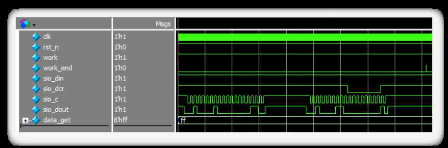
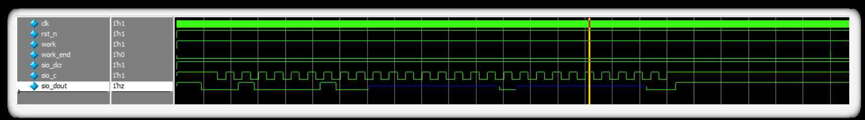
结果的话就展示一下modelsim的仿真图。
这部分是读的时序逻辑。
这部分是写的逻辑,由于修改模块输入后没有修改激励的输出,所以地址位和数据位是没有值的。
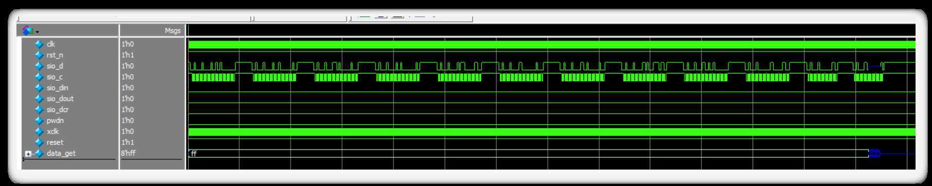
这是顶层模块的结果图。
在实际的板级测试时,数据基本上写读一致。由于只是测试了几个寄存器,也不确定是不是所有的都可行,这里就到此为止了。以后有时间可以应用到摄像头上。
原文:https://www.cnblogs.com/electricdream/p/13027348.html
内容总结
以上是互联网集市为您收集整理的基于SCCB协议的FPGA实现全部内容,希望文章能够帮你解决基于SCCB协议的FPGA实现所遇到的程序开发问题。 如果觉得互联网集市技术教程内容还不错,欢迎将互联网集市网站推荐给程序员好友。
内容备注
版权声明:本文内容由互联网用户自发贡献,该文观点与技术仅代表作者本人。本站仅提供信息存储空间服务,不拥有所有权,不承担相关法律责任。如发现本站有涉嫌侵权/违法违规的内容, 请发送邮件至 gblab@vip.qq.com 举报,一经查实,本站将立刻删除。
内容手机端
扫描二维码推送至手机访问。